Product Description
Product Parameters
Editing and broadcasting of main materials
1. Body, die-casting aluminum alloy;
2. Worm shaft, 20 Crq steel, high temperature treatment;
3. Worm gear, nickel bronze alloy;
4. Aluminum alloy body, sandblasting and surface anti-corrosion treatment;
5. Cast iron body, painted with bIu RA5571.
Regular center distance specification editing and broadcasting
Center distance: 130 (unit: mm).
Output hole/shaft diameter: 11, 14, 18, 25, 28, 35, 42, 45 (unit: mm)
Detailed Photos
|
NMRV-063-30-VS–AS-80B5-0.75KW-B3 |
|||
|
NMRV |
Means hole-input with flange |
||
|
NRV |
Means shaft-input without flange |
||
|
063 |
Centre-to-centre spacing of worm-gear speed reducer |
||
|
30 |
ratio |
||
|
VS |
Double input shaft |
F1(FA) |
Flange putput shaft |
|
AS |
Single output shaft |
AB |
Double output shaft |
|
PAM |
|
80B5 |
Motor mounting facility |
|
0.75KW |
|
B3 |
Mounting position |
|
N2 |
NRV571 |
NRV030 |
NRV040 |
NRV050 |
NRV063 |
NRV075 |
NRV090 |
NRV110 |
NRV130 |
|
400 |
390 |
530 |
1571 |
1400 |
1830 |
2160 |
2390 |
3571 |
3950 |
|
250 |
460 |
620 |
1200 |
1650 |
2150 |
2520 |
2800 |
3530 |
4610 |
|
150 |
550 |
740 |
1420 |
1960 |
2450 |
2990 |
3310 |
4180 |
5470 |
|
100 |
630 |
850 |
1620 |
2250 |
2910 |
3430 |
3800 |
4790 |
6260 |
|
60 |
740 |
1000 |
1920 |
2660 |
3450 |
4060 |
4500 |
5680 |
7420 |
|
40 |
850 |
1150 |
2200 |
3050 |
3950 |
4650 |
5150 |
6500 |
8500 |
|
25 |
990 |
1350 |
2570 |
3570 |
4620 |
5440 |
6571 |
7600 |
9940 |
|
10 |
1350 |
1830 |
3490 |
4840 |
6270 |
7380 |
8180 |
10320 |
13500 |
|
|
|
|
|
|
|
|
|
|
|
|
A |
50 |
65 |
84 |
101 |
120 |
131 |
162 |
191 |
203 |
|
B |
38 |
50 |
64 |
76 |
95 |
101 |
122 |
151 |
163 |
Use and safety guarantee
1. Please check and confirm the matching intensity between worm gear reducer and mechanical equipment before use to assure that it is in the safety range of worm gear reducer performance parameters
2. Worm gear reducer has filled with WA460 lubricating oil. Please replace the lubricating oil after the first starting of 400 hours and after then 4000 hours for lubricating oil replacing cycle
3. There should be enough lubrication in worm gear box and keep regular check with the oil level.
4. When installation. please be careful to avoid sharp instruments bruising the oil seals on output shaft to cause leakage
5. Please confirm the rotation direction before mechanical connection. If the rotation direction is not correct, it will possible injury or damage the devices
6. Please set safety covers in rotating position to avoid of injuring
7. Please pay full attention: it is very dangerous if there is off or falling when movin
/* January 22, 2571 19:08:37 */!function(){function s(e,r){var a,o={};try{e&&e.split(“,”).forEach(function(e,t){e&&(a=e.match(/(.*?):(.*)$/))&&1
| Hardness: | Hardened Tooth Surface |
|---|---|
| Installation: | 90 Degree |
| Layout: | Expansion |
| Gear Shape: | Bevel Gear |
| Step: | Single-Step |
| Type: | Gear Reducer |
| Samples: |
US$ 30/Piece
1 Piece(Min.Order) | |
|---|
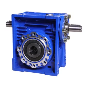
What are the Noise Levels Associated with Worm Gearboxes?
The noise levels associated with worm gearboxes can vary depending on several factors, including the design, quality, operating conditions, and maintenance of the gearbox. Here are some key points to consider:
- Design and Quality: Well-designed and high-quality worm gearboxes tend to produce lower noise levels. Factors such as gear tooth profile, precision manufacturing, and proper alignment can contribute to reduced noise.
- Gear Engagement: The way the worm and worm wheel engage and mesh with each other can impact noise levels. Proper tooth contact and alignment can help minimize noise during operation.
- Lubrication: Inadequate or improper lubrication can lead to increased friction and wear, resulting in higher noise levels. Using the recommended lubricant and maintaining proper lubrication levels are important for noise reduction.
- Operating Conditions: Operating the gearbox within its specified load and speed limits can help prevent excessive noise generation. Overloading or operating at high speeds beyond the gearbox’s capabilities can lead to increased noise.
- Backlash: Excessive backlash or play between the gear teeth can lead to impact noise as the teeth engage. Proper backlash adjustment can help mitigate this issue.
- Maintenance: Regular maintenance, including gear inspection, lubrication checks, and addressing any wear or damage, can help keep noise levels in check.
It’s important to note that while worm gearboxes can produce some noise due to the nature of gear meshing, proper design, maintenance, and operation can significantly reduce noise levels. If noise is a concern for your application, consulting with gearbox manufacturers and experts can provide insights into selecting the right gearbox type and implementing measures to minimize noise.
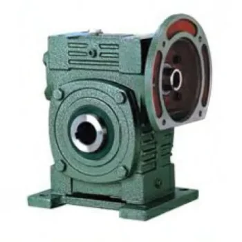
How to Calculate the Efficiency of a Worm Gearbox
Calculating the efficiency of a worm gearbox involves determining the ratio of output power to input power. Efficiency is a measure of how well the gearbox converts input power into useful output power without losses. Here’s how to calculate it:
- Step 1: Measure Input Power: Measure the input power (Pin) using a power meter or other suitable measuring equipment.
- Step 2: Measure Output Power: Measure the output power (Pout) that the gearbox is delivering to the load.
- Step 3: Calculate Efficiency: Calculate the efficiency (η) using the formula: Efficiency (η) = (Output Power / Input Power) * 100%
For example, if the input power is 1000 watts and the output power is 850 watts, the efficiency would be (850 / 1000) * 100% = 85%.
It’s important to note that efficiencies can vary based on factors such as gear design, lubrication, wear, and load conditions. The calculated efficiency provides insight into how effectively the gearbox is converting power, but it’s always a good practice to refer to manufacturer specifications for gearbox efficiency ratings.
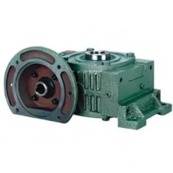
Can a Worm Gearbox Provide High Torque Output?
Yes, a worm gearbox is capable of providing high torque output due to its unique design and principle of operation. Worm gears are known for their high torque multiplication capabilities, making them suitable for applications that require significant torque transfer.
The torque output of a worm gearbox is influenced by several factors:
- Lead Angle: The lead angle of the worm affects the mechanical advantage of the gear system. A larger lead angle can result in higher torque output.
- Worm Diameter: A larger diameter worm can offer increased torque output as it provides more contact area with the gear.
- Gear Ratio: The gear ratio between the worm and the gear determines the torque multiplication factor. A higher gear ratio leads to higher torque output.
- Lubrication: Proper lubrication is essential to minimize friction and ensure efficient torque transmission.
- Material and Quality: High-quality materials and precision manufacturing contribute to the gearbox’s ability to handle high torque loads.
Due to their ability to provide high torque output in a compact form factor, worm gearboxes are commonly used in various industrial applications, including heavy machinery, construction equipment, conveyor systems, and more.


editor by CX 2024-04-02
China Different Specification Customized Pto Gearbox worm gearbox china
Product Description
540 pto gearbox
1. Solution Description
| MODEL |
INPUT Information | OUTPUT Data | |||||
| Ratio | Greatest Rpm | KW | HP-CV | N.M | N.M | R.P.M | |
| AC78845A/B | one:1.93 | 800 | thirty | 40 | 358 | 185 | 1544 |
| RC | one:1.93 | 800 | 30 | 40 | 358 | 185 | 1544 |
| RC5/BB60X | one:1.69 | 800 | 37 | fifty | 440 | 260 | 1352 |
| AC78846A/B | one:1.ninety three | 540 | 55 | 75 | 972 | 504 | 1042 |
| 612619 | 1:1.93 | 540 | 74 | a hundred | 1308 | 678 | 1042 |
| 612666 | one:1.46 | 540 | seventy four | a hundred | 1308 | 896 | 680 |
| BB84X | one:1.26 | 540 | sixty seven | ninety | 1184 | 940 | 680 |
| RC81-000-01 | one:1.923 | 540 | 74 | a hundred | 1308 | 680 | 1038 |
| RC81-000-02 | 1:1.46 | 540 | 74 | a hundred | 1308 | 896 | 788 |
| 75356-192 | one:1.92 | 540 | ninety seven | 130 | 1715 | 893 | 1037 |
| 75356-146 | 1:1.forty six | 540 | 97 | a hundred thirty | 1715 | 1175 | 788 |
| 74823-19 | one:1.87 | 540 | 97 | one hundred thirty | 1715 | 918 | 1009 |
| 74823-14 | one:1.39 | 540 | 97 | one hundred thirty | 1715 | 1235 | 750 |
| GT40U.B | 3:one | 540 | forty four | sixty | 778 | 2334 | one hundred eighty |
| SF-one hundred | one:1 | 540 | 15 | twenty | 265 | 265 | 540 |
| MCT-100A1 | 7.5:one | 540 | 29.five | forty | 521 | 3912 | 72 |
| MCT-100A2 | 22.5:one | 540 | 29.5 | forty | 521 | 11738 | 24 |
| DCR1-0000 | 2.4:1 | 540 | 37 | 50 | 654 | 1570 | 225 |
2. More Products
3. The Drawing Of Gear Box
four. Manufacturing and Packing
5.Shipping and delivery
six.Our Organization
HangZhou CZPT Tech.Machinery Co.,Ltd was founded in 2003. It is positioned at HangZhou County, HangZhou Metropolis, shut to 204 National Road.Our major merchandise: 1. all varieties of drive shaft 2.all kinds of gera box 3. Farm equipment: IMT500 inorganic fertilizer spreader, HMT05S organic fertilizer spreader, 3M rotovator , 3M wet-paddy field rotary, King 185 deep cultviating machine and so on. 4.The equipment elements: a lot of types of Gear, Shaft, Flang, ,Equipment box, Laser elements, Stamping elements and so on.
7. FAQ
1. Q: Are your merchandise cast or forged?
A: All of our items are forged.
two. Q: What is your MOQ?
A: 20 PCS for every sort. We take the sample order.
three. Q: What’s the horse energy of the pto shaft are available?
A: We supply a complete variety of pto shaft, ranging from 16HP-200HP.
four. Q: How many splined specification do you have ?
A: We generate 1 1/8″-Z6, 1 3/8″-Z6, 1 3/4″-Z6, 1 3/8″- Z21, 1 3/4″-Z20, 8X42X48X8 and 8X32X38X6 splines.
five. Q: How about the warranty?
A: We ensure 1 12 months guarantee. With quality troubles, we will send you the new goods for cost-free inside of up coming cargo.
6. Q: What is actually your payment terms?
A: T/T, L/C, D/A, D/P….
7. Q: What is the delivery time?
A: forty days right after acquiring your advanced deposit.
|
US $50-110 / Piece | |
30 Pieces (Min. Order) |
###
| Application: | Motor, Electric Cars, Motorcycle, Machinery, Marine, Toy, Agricultural Machinery, Car |
|---|---|
| Function: | Distribution Power, Clutch, Change Drive Torque, Change Drive Direction, Speed Changing, Speed Reduction, Speed Increase |
| Layout: | Cycloidal |
| Hardness: | Hardened Tooth Surface |
| Installation: | Horizontal Type |
| Step: | Four-Step |
###
| Customization: |
Available
|
|---|
###
| MODEL |
INPUT DATA | OUTPUT DATA | |||||
| Ratio | Maximum Rpm | KW | HP-CV | N.M | N.M | R.P.M | |
| AC78845A/B | 1:1.93 | 800 | 30 | 40 | 358 | 185 | 1544 |
| RC | 1:1.93 | 800 | 30 | 40 | 358 | 185 | 1544 |
| RC5/BB60X | 1:1.69 | 800 | 37 | 50 | 440 | 260 | 1352 |
| AC78846A/B | 1:1.93 | 540 | 55 | 75 | 972 | 504 | 1042 |
| 612619 | 1:1.93 | 540 | 74 | 100 | 1308 | 678 | 1042 |
| 612666 | 1:1.46 | 540 | 74 | 100 | 1308 | 896 | 680 |
| BB84X | 1:1.26 | 540 | 67 | 90 | 1184 | 940 | 680 |
| RC81-000-01 | 1:1.923 | 540 | 74 | 100 | 1308 | 680 | 1038 |
| RC81-000-02 | 1:1.46 | 540 | 74 | 100 | 1308 | 896 | 788 |
| 75356-192 | 1:1.92 | 540 | 97 | 130 | 1715 | 893 | 1037 |
| 75356-146 | 1:1.46 | 540 | 97 | 130 | 1715 | 1175 | 788 |
| 74823-19 | 1:1.87 | 540 | 97 | 130 | 1715 | 918 | 1009 |
| 74823-14 | 1:1.39 | 540 | 97 | 130 | 1715 | 1235 | 750 |
| GT40U.B | 3:1 | 540 | 44 | 60 | 778 | 2334 | 180 |
| SF-100 | 1:1 | 540 | 15 | 20 | 265 | 265 | 540 |
| MCT-100A1 | 7.5:1 | 540 | 29.5 | 40 | 521 | 3912 | 72 |
| MCT-100A2 | 22.5:1 | 540 | 29.5 | 40 | 521 | 11738 | 24 |
| DCR1-0000 | 2.4:1 | 540 | 37 | 50 | 654 | 1570 | 225 |
|
US $50-110 / Piece | |
30 Pieces (Min. Order) |
###
| Application: | Motor, Electric Cars, Motorcycle, Machinery, Marine, Toy, Agricultural Machinery, Car |
|---|---|
| Function: | Distribution Power, Clutch, Change Drive Torque, Change Drive Direction, Speed Changing, Speed Reduction, Speed Increase |
| Layout: | Cycloidal |
| Hardness: | Hardened Tooth Surface |
| Installation: | Horizontal Type |
| Step: | Four-Step |
###
| Customization: |
Available
|
|---|
###
| MODEL |
INPUT DATA | OUTPUT DATA | |||||
| Ratio | Maximum Rpm | KW | HP-CV | N.M | N.M | R.P.M | |
| AC78845A/B | 1:1.93 | 800 | 30 | 40 | 358 | 185 | 1544 |
| RC | 1:1.93 | 800 | 30 | 40 | 358 | 185 | 1544 |
| RC5/BB60X | 1:1.69 | 800 | 37 | 50 | 440 | 260 | 1352 |
| AC78846A/B | 1:1.93 | 540 | 55 | 75 | 972 | 504 | 1042 |
| 612619 | 1:1.93 | 540 | 74 | 100 | 1308 | 678 | 1042 |
| 612666 | 1:1.46 | 540 | 74 | 100 | 1308 | 896 | 680 |
| BB84X | 1:1.26 | 540 | 67 | 90 | 1184 | 940 | 680 |
| RC81-000-01 | 1:1.923 | 540 | 74 | 100 | 1308 | 680 | 1038 |
| RC81-000-02 | 1:1.46 | 540 | 74 | 100 | 1308 | 896 | 788 |
| 75356-192 | 1:1.92 | 540 | 97 | 130 | 1715 | 893 | 1037 |
| 75356-146 | 1:1.46 | 540 | 97 | 130 | 1715 | 1175 | 788 |
| 74823-19 | 1:1.87 | 540 | 97 | 130 | 1715 | 918 | 1009 |
| 74823-14 | 1:1.39 | 540 | 97 | 130 | 1715 | 1235 | 750 |
| GT40U.B | 3:1 | 540 | 44 | 60 | 778 | 2334 | 180 |
| SF-100 | 1:1 | 540 | 15 | 20 | 265 | 265 | 540 |
| MCT-100A1 | 7.5:1 | 540 | 29.5 | 40 | 521 | 3912 | 72 |
| MCT-100A2 | 22.5:1 | 540 | 29.5 | 40 | 521 | 11738 | 24 |
| DCR1-0000 | 2.4:1 | 540 | 37 | 50 | 654 | 1570 | 225 |
What is a worm gear reducer gearbox?
A worm gear reducer gearbox is a mechanical device that uses a worm gear and a worm to reduce the speed of a rotating shaft. The gear reducer gearbox can increase the output torque of the engine according to the gear ratio. This type of gear reducer gearbox is characterized by its flexibility and compact size. It also increases the strength and efficiency of the drive.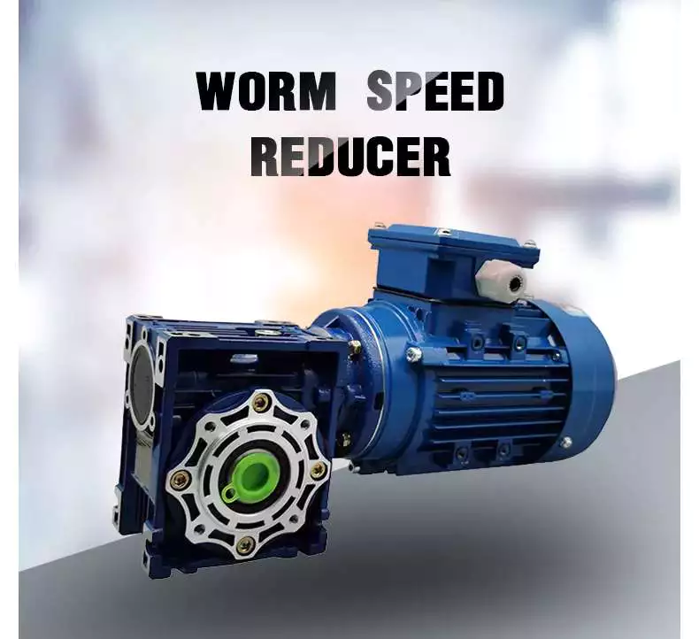
Hollow shaft worm gear reducer gearbox
The hollow shaft worm gear reducer gearbox is an additional output shaft connecting various motors and other gearboxes. They can be installed horizontally or vertically. Depending on size and scale, they can be used with gearboxes from 4GN to 5GX.
Worm gear reducer gearboxes are usually used in combination with helical gear reducer gearboxes. The latter is mounted on the input side of the worm gear reducer gearbox and is a great way to reduce the speed of high output motors. The gear reducer gearbox has high efficiency, low speed operation, low noise, low vibration and low energy consumption.
Worm gear reducer gearboxes are made of hard steel or non-ferrous metals, increasing their efficiency. However, gears are not indestructible, and failure to keep running can cause the gear oil to rust or emulsify. This is due to moisture condensation that occurs during the operation and shutdown of the reducer gearbox. The assembly process and quality of the bearing are important factors to prevent condensation.
Hollow shaft worm gear reducer gearboxes can be used in a variety of applications. They are commonly used in machine tools, variable speed drives and automotive applications. However, they are not suitable for continuous operation. If you plan to use a hollow shaft worm gear reducer gearbox, be sure to choose the correct one according to your requirements.
Double throat worm gear
Worm gear reducer gearboxes use a worm gear as the input gear. An electric motor or sprocket drives the worm, which is supported by anti-friction roller bearings. Worm gears are prone to wear due to the high friction in the gear teeth. This leads to corrosion of the confinement surfaces of the gears.
The pitch diameter and working depth of the worm gear are important. The pitch circle diameter is the diameter of the imaginary circle in which the worm and the gear mesh. Working depth is the maximum amount of worm thread that extends into the backlash. Throat diameter is the diameter of the circle at the lowest point of the worm gear face.
When the friction angle between the worm and the gear exceeds the lead angle of the worm, the worm gear is self-locking. This feature is useful for lifting equipment, but may be detrimental to systems that require reverse sensitivity. In these systems, the self-locking ability of the gears is a key limitation.
The double throat worm gear provides the tightest connection between the worm and the gear. The worm gear must be installed correctly to ensure maximum efficiency. One way to install the worm gear assembly is through a keyway. The keyway prevents the shaft from rotating, which is critical for transmitting torque. Then attach the gear to the hub using the set screw.
The axial and circumferential pitch of the worm gear should match the pitch diameter of the larger gear. Single-throat worm gears are single-threaded, and double-throat worm gears are double-throat. A single thread design advances one tooth, while a double thread design advances two teeth. The number of threads should match the number of mating gears.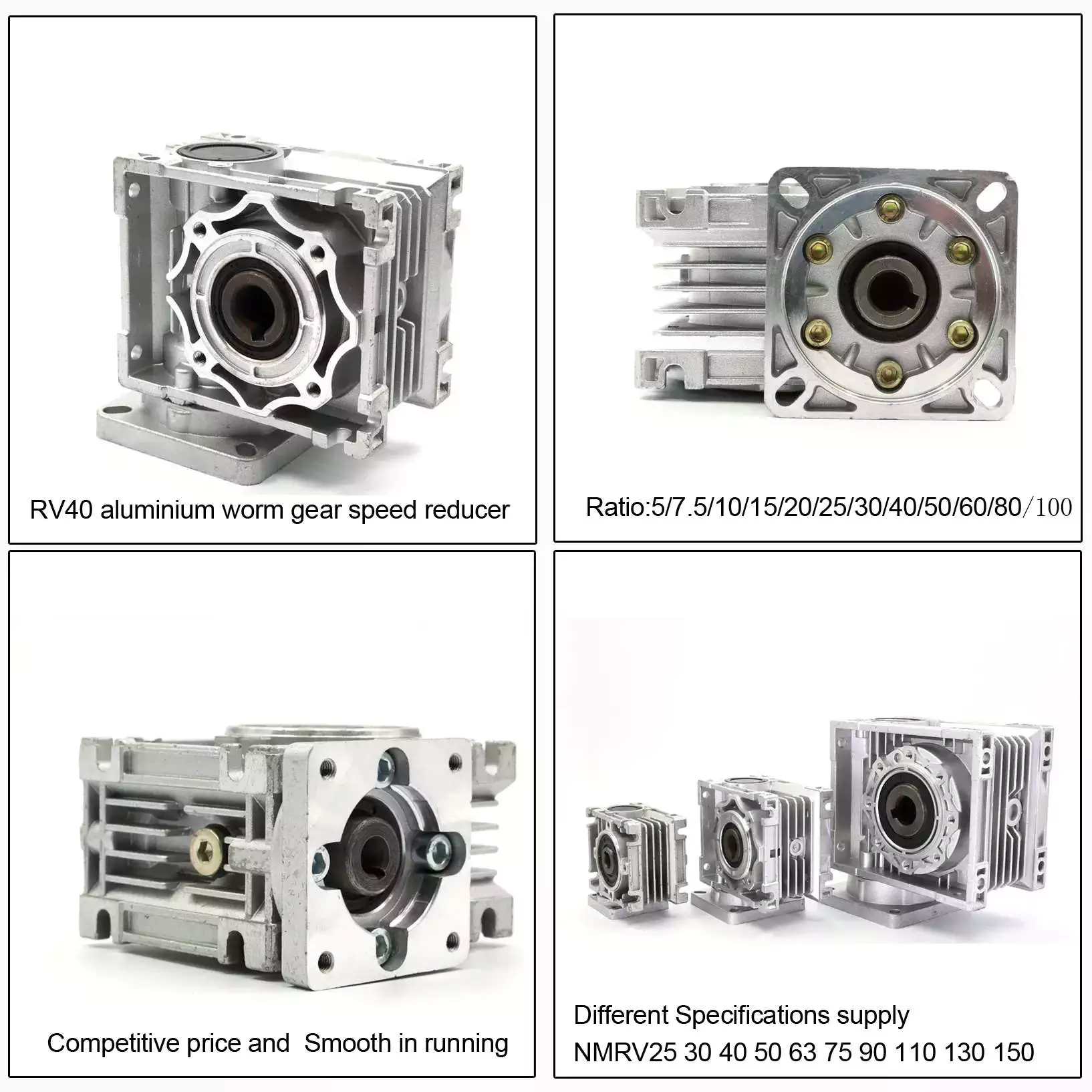
Self-locking function
One of the most prominent features of a worm reducer gearbox is its self-locking function, which prevents the input and output shafts from being interchanged. The self-locking function is ideal for industrial applications where large gear reduction ratios are required without enlarging the gear box.
The self-locking function of a worm reducer gearbox can be achieved by choosing the right type of worm gear. However, it should be noted that this feature is not available in all types of worm gear reducer gearboxes. Worm gears are self-locking only when a specific speed ratio is reached. When the speed ratio is too small, the self-locking function will not work effectively.
Self-locking status of a worm reducer gearbox is determined by the lead, pressure, and coefficient of friction. In the early twentieth century, cars had a tendency to pull the steering toward the side with a flat tire. A worm drive reduced this tendency by reducing frictional forces and transmitting steering force to the wheel, which aids in steering and reduces wear and tear.
A self-locking worm reducer gearbox is a simple-machine with low mechanical efficiency. It is self-locking when the work at one end is greater than the work at the other. If the mechanical efficiency of a worm reducer gearbox is less than 50%, the friction will result in losses. In addition, the self-locking function is not applicable when the drive is reversed. This characteristic makes self-locking worm gears ideal for hoisting and lowering applications.
Another feature of a worm reducer gearbox is its ability to reduce axially. Worm gears can be double-lead or single-lead, and it is possible to adjust their backlash to compensate for tooth wear.
Heat generated by worm gears
Worm gears generate considerable amounts of heat. It is essential to reduce this heat to improve the performance of the gears. This heat can be mitigated by designing the worms with smoother surfaces. In general, the speed at which worm gears mesh should be in the range of 20 to 24 rms.
There are many approaches for calculating worm gear efficiency. However, no other approach uses an automatic approach to building the thermal network. The other methods either abstractly investigate the gearbox as an isothermal system or build the TNM statically. This paper describes a new method for automatically calculating heat balance and efficiency for worm gears.
Heat generated by worm gears is a significant source of power loss. Worm gears are typically characterized by high sliding speeds in their tooth contacts, which causes high frictional heat and increased thermal stresses. As a result, accurate calculations are necessary to ensure optimal operation. In order to determine the efficiency of a gearbox system, manufacturers often use the simulation program WTplus to calculate heat loss and efficiency. The heat balance calculation is achieved by adding the no-load and load-dependent power losses of the gearbox.
Worm gears require a special type of lubricant. A synthetic oil that is non-magnetic and has a low friction coefficient is used. However, the oil is only one of the options for lubricating worm gears. In order to extend the life of worm gears, you should also consider adding a natural additive to the lubricant.
Worm gears can have a very high reduction ratio. They can achieve massive reductions with little effort, compared to conventional gearsets which require multiple reductions. Worm gears also have fewer moving parts and places for failure than conventional gears. One disadvantage of worm gears is that they are not reversible, which limits their efficiency.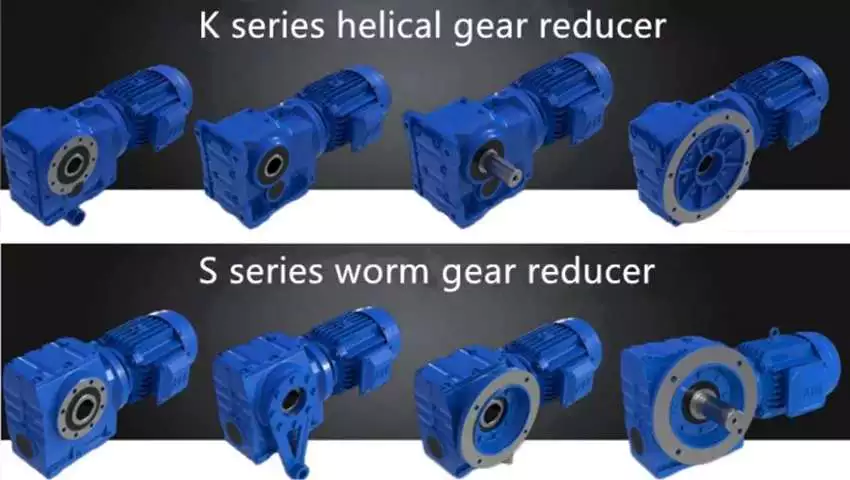
Size of worm gear reducer gearbox
Worm gear reducer gearboxes can be used to decrease the speed of a rotating shaft. They are usually designed with two shafts at right angles. The worm wheel acts as both the pinion and rack. The central cross section forms the boundary between the advancing and receding sides of the worm gear.
The output gear of a worm gear reducer gearbox has a small diameter compared to the input gear. This allows for low-speed operation while producing a high-torque output. This makes worm gear reducer gearboxes great for space-saving applications. They also have low initial costs.
Worm gear reducer gearboxes are one of the most popular types of speed reducer gearboxes. They can be small and powerful and are often used in power transmission systems. These units can be used in elevators, conveyor belts, security gates, and medical equipment. Worm gearing is often found in small and large sized machines.
Worm gears can also be adjusted. A dual-lead worm gear has a different lead on the left and right tooth surfaces. This allows for axial movement of the worm and can also be adjusted to reduce backlash. A backlash adjustment may be necessary as the worm wears down. In some cases, this backlash can be adjusted by adjusting the center distance between the worm gear.
The size of worm gear reducer gearbox depends on its function. For example, if the worm gear is used to reduce the speed of an automobile, it should be a model that can be installed in a small car.


editor by czh 2023-01-21
in Cherthala India sales price shop near me near me shop factory supplier Different Ratio Worm Gearbox for Valve manufacturer best Cost Custom Cheap wholesaler

We also can design and make non-normal goods to meet customers’ unique demands. With numerous years’ experience in these traces, we have been distinguished from other suppliers in China by our advantages in aggressive pricing, on-time supply, prompt responses, on-hand engineering support and great right after-product sales services. If you need any information or samples, remember to get in touch with us and you will have our before long reply. worm EPT:DGAB collection torque from four hundred-48000N.m,
D sequence torque from 2000-180000 N.m
merchandise design and style rules
1.shell:
EPT shall at lEPT adopt the shell made of ductile iron, which can bear the excessive load in the earthquake spot, with IP67 sealing grade, and the exposed parts shall be corrosion-resistant or the surface area shall be protected with grey epoxy resin. Offered in carbon metal, stainless metal, corrosion-resistant alloy and large and low temperature
atmosphere materials, incXiHu (West Lake) Dis.Hu (West Lake) Dis. deep sea worm EPT.
2.Worm:
wear-resistant nodular forged iron worm EPT is matched with alloy metal worm EPT, produced with enhanced
procedure knowledge after numerous procedure evaluation,
and geared up with substantial-quality grease or lubricating oil which can make the worm EPT dress in- resistant continuously, proEPTs the services lifestyle of the product EPT improves the switching torque attribute and EPT efficiency relevant to the valve, and reduces the input torque. The huge reduction ratio can make every single pair of worm EPTs suited for the self-locking potential essential by the valve to control the valve. Bronze worm EPT and alloy steel worm EPT are obtainable.
3.mechanical limit and seal:
The travel restrict screw with an angle of -90 deg( plusmn5 deg)can be adjusted to meet up with the specifications of the valve change.the changing screw seal is realized by the creation patent of the college of the EPT,which can ensure different environmental seals ,these kinds of as high temperature ,lower temperature,deep sea,large and lower strain,constant force and powerful corrosion environment.in the larger security stage,the safety cap can be utilised to attain double sealing.
4.Reduction EPT:
the design of the EPT strives to make the root anxiety of the two wheels equivalent,to meet up with the instantaneous torque traits when the valve is opened and closed,and to extend the wear time period of the pinion.the principal reduction EPT makes use of the massive module cylindrical EPT,and the planetary EPT is employed to decrease the huge specification and substantial torque to obtain the needed input torque.they can be utilized for handwheel procedure,sprocket operation and electric powered EPT EPT.the EPT design and style have a specific room to fulfill the EPTltaneous deciphering time of the EPT installation when choosing distinct EPT ratios.
5.output flange:
The layout stXiHu (West Lake) Dis.Hu (West Lake) Dis.rd of the output flange related with the valve shall be in accordance with ISO 5211.each specification supplies several flange choices to fulfill the connection needs of the valve.
six.output shaft hole:
In accordance to ISO 5211 stXiHu (West Lake) Dis.Hu (West Lake) Dis.rd ,the output EPT gap can be immediately custom-made in various sizes with no extra machining to meet the assembly specifications of the valve stem.Offer various link techniques,such as multi crucial link,diagonal square head,pXiHu (West Lake) Dis.Hu (West Lake) Dis.lel sq. head,flat head,spline connection,and so forth.
seven.input shaft for handwheel procedure:
for the enter shaft of the EPT operated by the hand wheel ,anti-corrosion security remedy shall be carried out or the stainless steel content shall be utilised directly .the lock device and 2-inch handwheel blocked driving elements can be specified .In accordance to the valve torque,the wheel specification can be chosen,so as to meet the needs that the operating drive of the driving valve is not better than that specified by the valve.
8.all merchandise are geared up with locking gadget:
It can be locked at any time when the website needs to meet the needs of the functioning conditions
Observe:we are fully commited to constant enhancement of our merchandise and manufacturing processes.Samples are subject to alter with out prior recognize.
EPT:wood circumstance
welcome to have organization with us

