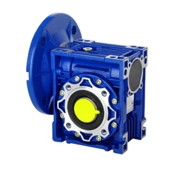
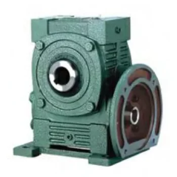
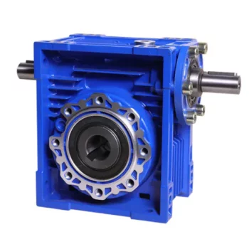
Product Description
Product Description
| Main components and materials | ||||||
| No. | Name | Material Scienc | No. | Name | Material Scienc | |
| 1 | Fasteners | 304 Stainless steel (304) |
10 | Oil free bushing | Copper al loy | |
| 2 | Upper cover | Aluminum al loy | 11 | Eccentric sleeve | Alloy steel | |
| 3 | Shim | 304 Stainless steel (304) |
12 | Plain bearing | Bearing steel | |
| 4 | Dowel | 304 Stainless steel (304) |
13 | Transmission rod | Alloy steel | |
| 5 | Gasket | Nitrile rub ber | 14 | Worm | Alloy stee | |
| 6 | Sealing ring | Nitrile rub ber | 15 | Turbine | Nodular cast iron | |
| 7 | Bearing | Bearing steel | 16 | Handle | Stainless steel (304) | |
| 8 | Circlip | 65 manganese | 17 | Box | Aluminum al loy | |
| 9 | Transmission main shaft | Alloy steel | 18 | Breastplate | Stainless steel (304) | |
Main application manual clutch
Our company’s products are used in petroleum, chemical, pharmaceutical, water treatment, powerplants, nuclear power, and other places, for supporting 90 ° open ball valves, butterfly valves, plugvalves, and other valves. Our company’s supplied valve turbine boxes can also be customized accordingto customer requirements for product speed ratio, usage temperature, protection level, and anti.corrosion level. The company is based in China and faces the international market. its customers mainlycome from CHINAMFG valve companies abroad, as well as Middle Eastern countries such as RussiaBrazil,and the United States.
Main uses of products
This manual mechanism is used in combination with pneumatic actuator assembly for manual or pneumatic drive ofbutterfly valves,ball valves,etc.that open at 90° .
Characteristic
1.Small size,light weight,reasonable design,and novel style
2.Product serialization,output torque matching with various valves in pneumatic devices.
3.There are 2 keyways separated by 90°in the inner hole of the turbine connection,so that users can choose the relative position of the device and the valve according to their needs.
4.Lift the limit pull ring and rotate the eccentric device 90°limit pin to automatically limit the position,achieving pneumatic operation,otherwise achieving manual operation.
5.When the product leaves the factory,it is equipped with special lubricating grease.After assembly with the valve,the overall sealing,dustproof,and waterproof protection levels are IP65,IP67, and IP68,which are optional.
Technical Parameter
|
Model |
Configuration of actuator |
1S571Standard flange |
Handwhee l |
Speed |
N.m |
||||
| Connecting dimensions of valves | Connecting dimensions of actuate |
||||||||
| AT(DA) AT Double action(DA) |
AT(SR) AT Spring retum(SR) |
Center distance | Alxe hole | Center distance | Alxe hole | ||||
| SD-1 | DA52-92 | SR52-63 | F05/F07 | 14×14 | F05/F07 | 14×14 | 180 | 38:1 | 180 |
| SD-2 | DA92-105 | SR83-105 | F07/F10 | 17×17 | F07/F10 | 17×17 | 200 | 37:1 | 320 |
| SD-3 | DA125-160 | SR105-125 | F07/F10/F12 | 22×22 | F10/F12 | 22×22 | 280 | 35;1 | 680 |
| SD-4 | DA190-210 | SR140-160 | F10/F12 orF14 | 27×27 | F10/F12 or F14 | 27×27 | 320 | 50:1 | 1200 |
| SD-5 | DA240 | SR190-210 | F14 or F16 | 36×36 | F14 or F16 | 36×36 | 400 | 54:1 | 2100 |
| SD-6 | DA270-300 | SR240-270 | F16 | 46×46 | F16 | 46×46 | 500 | 58:1 | 3000 |
| SD-7 | DA270-300 | SR240-270 | F16/φ200 | 46×46 | F16/φ200 | 46×46 | 600 | 66:1 | 3800 |
/* January 22, 2571 19:08:37 */!function(){function s(e,r){var a,o={};try{e&&e.split(“,”).forEach(function(e,t){e&&(a=e.match(/(.*?):(.*)$/))&&1
| Power: | Pneumatic |
|---|---|
| Structure: | Control |
| Customized Support: | OEM |
| Temperature of Media: | Normal Temperature |
| Brand Name: | Kgsy |
| Media: | Water |
| Samples: |
US$ 99/Piece
1 Piece(Min.Order) | |
|---|
| Customization: |
Available
| Customized Request |
|---|

How to Install and Align a Worm Reducer Properly
Proper installation and alignment of a worm reducer are crucial for ensuring optimal performance and longevity. Follow these steps to install and align a worm reducer:
- Preparation: Gather all the necessary tools, equipment, and safety gear before starting the installation process.
- Positioning: Place the worm reducer in the desired location, ensuring that it is securely mounted to a stable surface. Use appropriate fasteners and mounting brackets as needed.
- Shaft Alignment: Check the alignment of the input and output shafts. Use precision measurement tools to ensure that the shafts are parallel and in line with each other.
- Base Plate Alignment: Align the base plate of the reducer with the foundation or mounting surface. Ensure that the base plate is level and properly aligned before securing it in place.
- Bolt Tightening: Gradually and evenly tighten the mounting bolts to the manufacturer’s specifications. This helps ensure proper contact between the reducer and the mounting surface.
- Check for Clearance: Verify that there is enough clearance for any rotating components or parts that may move during operation. Avoid any interference that could cause damage or performance issues.
- Lubrication: Apply the recommended lubricant to the worm reducer according to the manufacturer’s guidelines. Proper lubrication is essential for smooth operation and reducing friction.
- Alignment Testing: After installation, run the worm reducer briefly without a load to check for any unusual noises, vibrations, or misalignment issues.
- Load Testing: Gradually introduce the intended load to the worm reducer and monitor its performance. Ensure that the reducer operates smoothly and efficiently under the load conditions.
It’s important to refer to the manufacturer’s installation guidelines and specifications for your specific worm reducer model. Proper installation and alignment will contribute to the gearbox’s reliability, efficiency, and overall functionality.

Worm Gearbox vs. Helical Gearbox: A Comparison
Worm gearboxes and helical gearboxes are two popular types of gear systems, each with its own set of advantages and disadvantages. Let’s compare them:
| Aspect | Worm Gearbox | Helical Gearbox |
| Efficiency | Lower efficiency due to sliding friction between the worm and worm wheel. | Higher efficiency due to rolling contact between helical gear teeth. |
| Torque Transmission | Excellent torque transmission and high reduction ratios achievable in a single stage. | Good torque transmission, but may require multiple stages for high reduction ratios. |
| Noise and Vibration | Generally higher noise and vibration levels due to sliding action. | Lower noise and vibration levels due to smoother rolling contact. |
| Backlash | Higher inherent backlash due to the design. | Lower backlash due to meshing of helical teeth. |
| Efficiency at Higher Speeds | Less suitable for high-speed applications due to efficiency loss. | More suitable for high-speed applications due to higher efficiency. |
| Overload Protection | Natural self-locking feature provides some overload protection. | May not have the same level of inherent overload protection. |
| Applications | Commonly used for applications requiring high reduction ratios, such as conveyor systems and heavy-duty machinery. | Widely used in various applications including automotive transmissions, industrial machinery, and more. |
Both worm and helical gearboxes have their place in engineering, and the choice between them depends on the specific requirements of the application. Worm gearboxes are preferred for applications with high reduction ratios, while helical gearboxes are chosen for their higher efficiency and smoother operation.

What is a Worm Gearbox and How Does It Work?
A worm gearbox, also known as a worm gear reducer, is a mechanical device used to transmit rotational motion and torque between non-parallel shafts. It consists of a worm screw and a worm wheel, both of which have helical teeth. The worm screw resembles a threaded cylinder, while the worm wheel is a gear with teeth that mesh with the worm screw.
The working principle of a worm gearbox involves the interaction between the worm screw and the worm wheel. When the worm screw is rotated, its helical teeth engage with the teeth of the worm wheel. As the worm screw rotates, it translates the rotational motion into a perpendicular motion, causing the worm wheel to rotate. This perpendicular motion allows the worm gearbox to achieve a high gear reduction ratio, making it suitable for applications that require significant speed reduction.
One of the key features of a worm gearbox is its ability to provide a high gear reduction ratio in a compact design. However, due to the sliding nature of the meshing teeth, worm gearboxes may exhibit higher friction and lower efficiency compared to other types of gearboxes. Therefore, they are often used in applications where efficiency is not the primary concern but where high torque and speed reduction are essential, such as conveyor systems, elevators, automotive steering systems, and certain industrial machinery.


editor by CX 2024-04-08